ORTHOLETTER

Lower limb orthosis with polypropylene articulation

Page 2


Thermal molding and cutting of the femoral segment


2 polypropylene sheets are cut according to the schematic in Figure 1:
· Small sheet (A) (5mm thick) for the lower part and joint
· Big sheet (B) (4mm thick), for the whole segment.

Figure 1

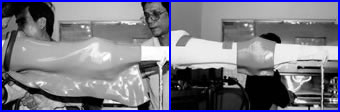
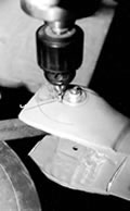
A sock, or tubular jersey, is put on the positive mold before the molding to draw the air away during the process. If needed, microcellular moss is placed on the joints and on the sidebars of the device in order to make it more rigid. Both sheets are thermally molded, one on top of the other, the small one first, than the larger, as shown below.

Both sheets must be carefully molded together to reduce any air bubbles. During the vacuum molding process, pull both ends of the two sheets on the plaster mold to ensure a better connection of the two pieces

Note : The rigidity that results from the increased thickness of both polypropylene sheets will assist the wearers by providing improved knee stability once the straps are fastened.

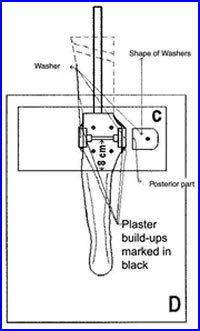
The femoral section is cut off the cast and will be trimmed around the joint area as explained in the next sections of the article.

Thermal molding and cutting of the lower leg segment
Two polypropylene washers, as thick as the 2 superimposed sheets of the femoral segment, are placed over each side of the joint alignment guide with the flat side of the washer at the back (shown in Figure 2). The purpose of this is to replace the joint heads of the femoral section, so the joint heads of the lower leg section will be at the proper diameter.

For the lower leg segment, 2 polypropylene sheets, of 5 mm each, are cut according to the schematic in Figure 2:
· Small sheet (C), for the upper part of the joint
· Big sheet (D), for the whole leg and foot segment

The thermal molding process is the same (take the same precautions) as for the femoral segment, starting with the small sheet, around the knee.


Figure 2

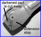
Design of the extension stops

The 4 anterior stops are designed in the sagittal plane with a 45° angle. The stops protrude anteriorly and make contact with each other when the user goes into full extension. The diagrams below show the preparation of these stops (also see Figure 3 - pg. 3).

Joint heads and extension stops cut

 Joint heads, on each side of the lower part of the femoral segment and of the upper part of the leg segment, are marked as shown to prepare for the cutting of the joint heads and extension stops.


An 8 mm hole is made in the orthosis axis (in the centre of joint heads), and the circumference of the heads (35 mm diameter) is cut with a 5 mm drill as shown on the right.


The extension stops are then cut according to the marked plastic by using the saw, as shown below.


Page 2

 PAGE 3  PAGE 1   ARTICLE PAGE